Why Wireless Chargers Throttle: Coils, Heat and Design
Every wireless charger is fast for the first five minutes. What separates a well-engineered model from a generic one is what happens after. This guide explains the physics behind throttling and the design choices that control it, so buyers can read a sample test like an engineer.
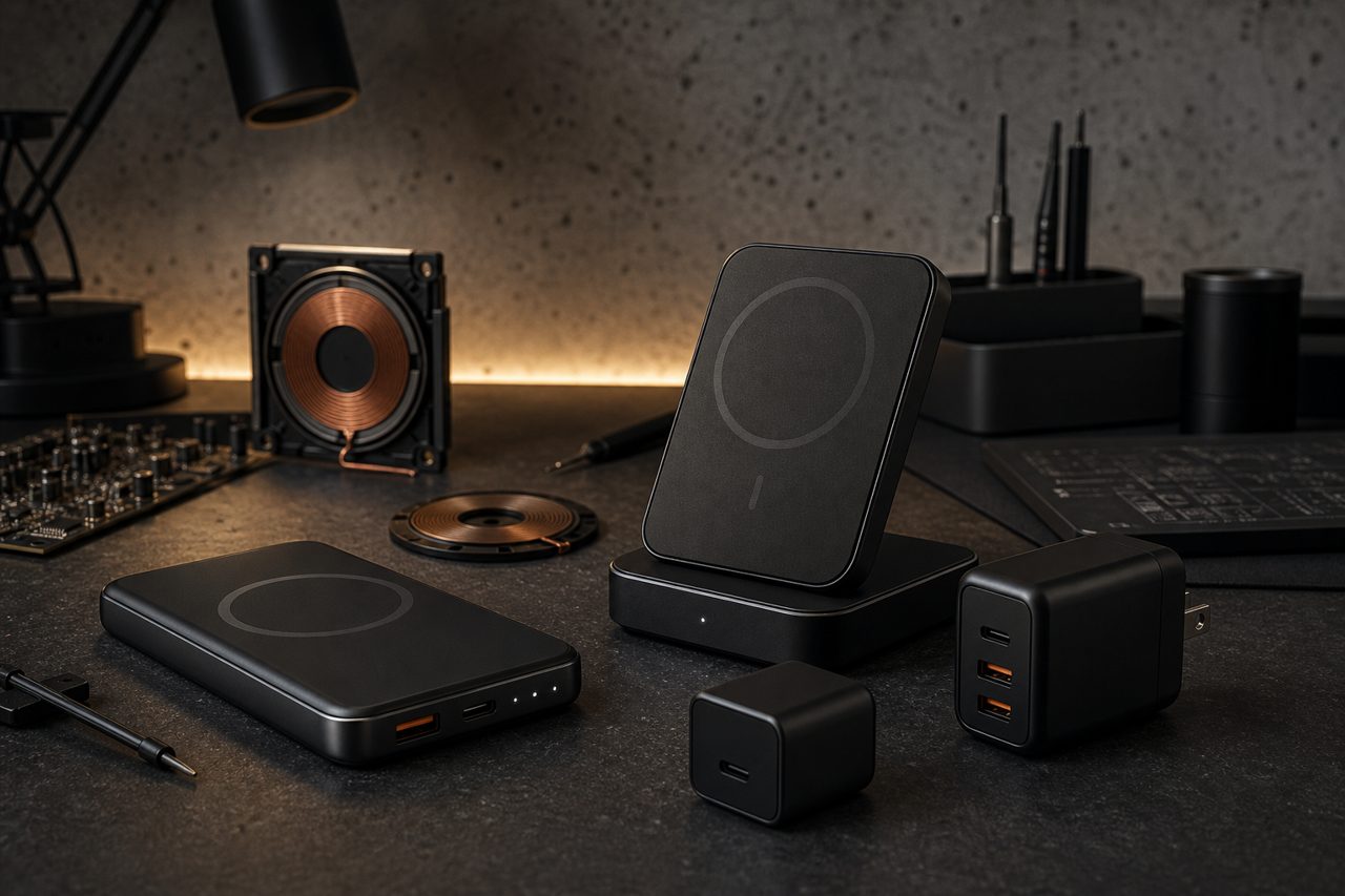
The commercial backdrop makes the topic urgent rather than academic. The global wireless charger market is forecast to reach USD 19.0 billion by 2030, growing at 22.9% a year (Grand View Research, 2025), and the Qi2.2 specification has lifted the wireless power ceiling to 25W (Wireless Power Consortium, 2025). Higher printed wattages raise customer expectations, and customer expectations collide with a physical fact: inductive charging turns some of its energy into heat, and heat caps the speed. A buyer who understands where that heat comes from can predict which products will earn good reviews before reading any.
What throttling actually is
Throttling is temperature derating: the deliberate reduction of charging power as temperatures climb. It is a protection mechanism, not a malfunction. Two devices sit at the ends of the wireless link, and both defend themselves. The charger derates to protect its own coil and driver electronics; the phone derates to protect its battery, because lithium cells age faster and charge less willingly when warm. Whichever device hits its limit first sets the speed for both.
This is why a wireless charger cannot be evaluated in isolation. It is one component in a thermal chain that includes the phone's receiver coil, the phone's battery, the case in between, and the air around both. A charger design that runs cool gives the chain more headroom; a charger design that runs hot forces the phone to pull back even if the charger itself could deliver more.
For a seller, the practical translation is direct: sustained speed, not peak speed, is the specification customers actually experience. Reviews that say fast at first, then slow are describing a thermal design that ran out of headroom.
Coils and alignment: where the heat is born
Inductive charging transfers energy across an air gap between two coils. Transfer efficiency depends almost entirely on how well those coils are coupled, and coupling collapses with misalignment. Off-center or tilted coils waste energy as eddy losses and stray heating in whatever metal or ferrite sits nearby. Wasted energy is not lost quietly; it becomes heat in exactly the wrong place, between the two devices that are trying to manage their temperature.
This is why the magnetic ring matters more than most buyers assume. The magnet array introduced with the magnetic power profile and carried into Qi2 holds the receiver coil in near-perfect alignment for the whole session, which keeps coupling high and waste low. Alignment is a cooling feature as much as a convenience feature. The Qi2.2 update to 25W (Wireless Power Consortium, 2025) raises the stakes: more transferred power means more heat to manage, and designs that relied on low power to hide weak coupling will expose themselves at the higher tier.
Coil count is the second variable. A single large coil is simple and efficient when the device sits centered on it. Multi-coil pads promise positional freedom, but only one coil couples at a time, and the others add switching complexity and surface area where losses can appear. A well-made single-coil magnetic charger will usually outperform a cheap three-coil pad, because its one coil is always where the phone is.
Heat paths: the design decisions buyers never see
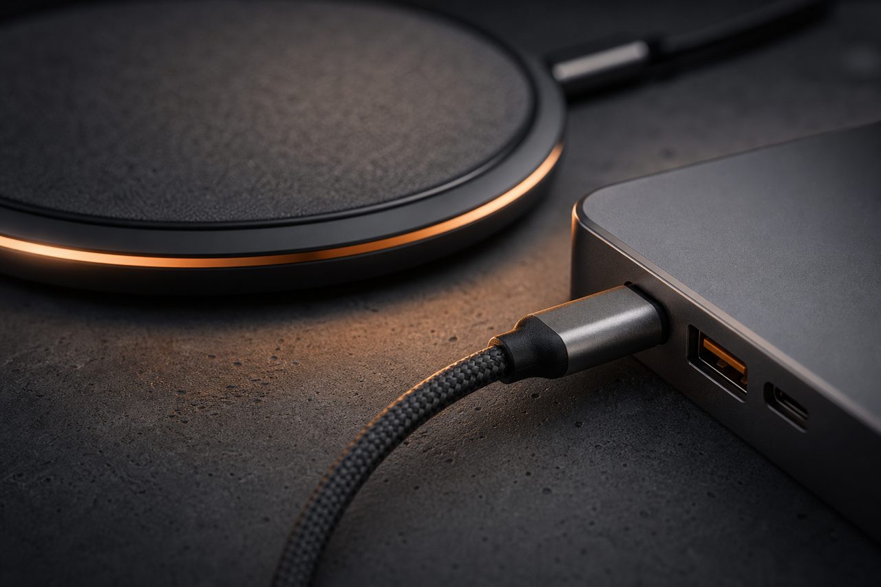
Once heat exists, design determines whether it leaves quickly or accumulates. The main levers, in order of impact:
- Coil-to-housing stack. A thermal pad from the coil's back into the housing conducts heat out; a hollow air gap insulates it in place.
- Housing material. Aluminum spreads heat across the whole body and feels warm to the touch; thick plastic traps it at the coil.
- Ventilation geometry. Vents near the coil let convection work; sealed decorative housings turn the pad into a heat store.
- Standby draw. A charger that idles warm is burning headroom before charging starts.
- Foreign object detection. FOD should cut power when metal is detected between the coils; a design that ignores it turns a card clip into a heating element.
None of these appears on a spec sheet, which is precisely why a sample test matters more for wireless chargers than for wired ones.
Reading the failures: symptom to cause to check
Field complaints cluster into recognizable patterns, and each pattern points at a specific design decision:
| Symptom in reviews | Likely cause | Design fix | Buyer's check |
|---|---|---|---|
| Fast for minutes, then slows sharply | Heat accumulating at coil or battery | Thermal pad, metal housing, ventilation | Compare negotiated power at minute 0 and minute 20 |
| Only charges fast in one exact spot | Single coil with tight alignment tolerance | Magnet ring for guided alignment | Offset the phone a few millimeters and retest |
| Slower or hotter through a case | Weak coupling or heat trapped by the case | Coil tuning for realistic case stack, TIM improvement | Repeat the 20-minute test through a typical case |
| Pad warm while idle | High standby draw | Lower-power idle mode | Measure idle draw after two hours on the outlet |
| Hot spots with metal objects nearby | FOD missing or delayed | Responsive FOD cutoff | Place a metal card clip between coil and phone; expect shutdown |
A five-measurement bench protocol
The whole evaluation fits in an afternoon with a protocol meter and a thermometer:
- Record the negotiated power the moment charging starts, and again after twenty minutes at full load. The gap between the two is the throttling profile the customer will feel.
- Log housing surface temperature at the coil point and at the base at the twenty-minute mark.
- Repeat the twenty-minute test through a case of realistic thickness; most customers never charge bare devices.
- Deliberately offset the phone a few millimeters and confirm the charger either maintains safe output or refuses cleanly, rather than cooking the offset position.
- Measure idle draw after the charger has sat plugged in for two hours.
Five numbers summarize the thermal design more honestly than any spec sheet. Samples of stock models ship from a single piece, so this loop costs days, not weeks.
Where design meets sourcing
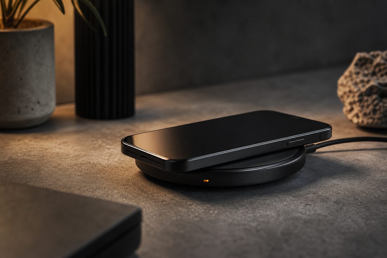
Thermal quality is set at the design stage, which makes it a sourcing decision as much as an engineering one. On stock models, the bench protocol above sorts the lineup quickly. On customized models, the levers open up: housing material, coil specification, magnet fixture geometry and firmware derating curves are all configurable through our OEM process, with sampling in 7-12 days and volume production in 25-35 days. Buyers moving from stock validation to branding can review the OEM/ODM process and the current charging lineup; the standards side is covered in the Qi2 sourcing guide.
FAQ
Why does a wireless charger slow down after a few minutes?
Thermal derating. Inductive transfer always loses some energy as heat, and both charger and phone reduce power as temperatures rise to protect the battery and electronics. A charger that holds its speed is not stronger; it is better-cooled, with efficient coils, good alignment and a housing that moves heat out.
Do magnetic Qi2 chargers run cooler than ordinary wireless chargers?
Usually yes: the magnet ring keeps the coils aligned for the whole session, and aligned coils waste less energy as heat. Alignment is a cooling feature as much as a convenience. The 25W ceiling of Qi2.2 makes thermal design more important, since more transferred power means more heat to manage.
What should buyers test on wireless charger samples before ordering?
Negotiated power at start and after twenty minutes at full load, surface temperature, the same test through a realistic case, behavior with the phone deliberately offset, and idle draw. Five measurements separate a well-engineered charger from a good-looking one.